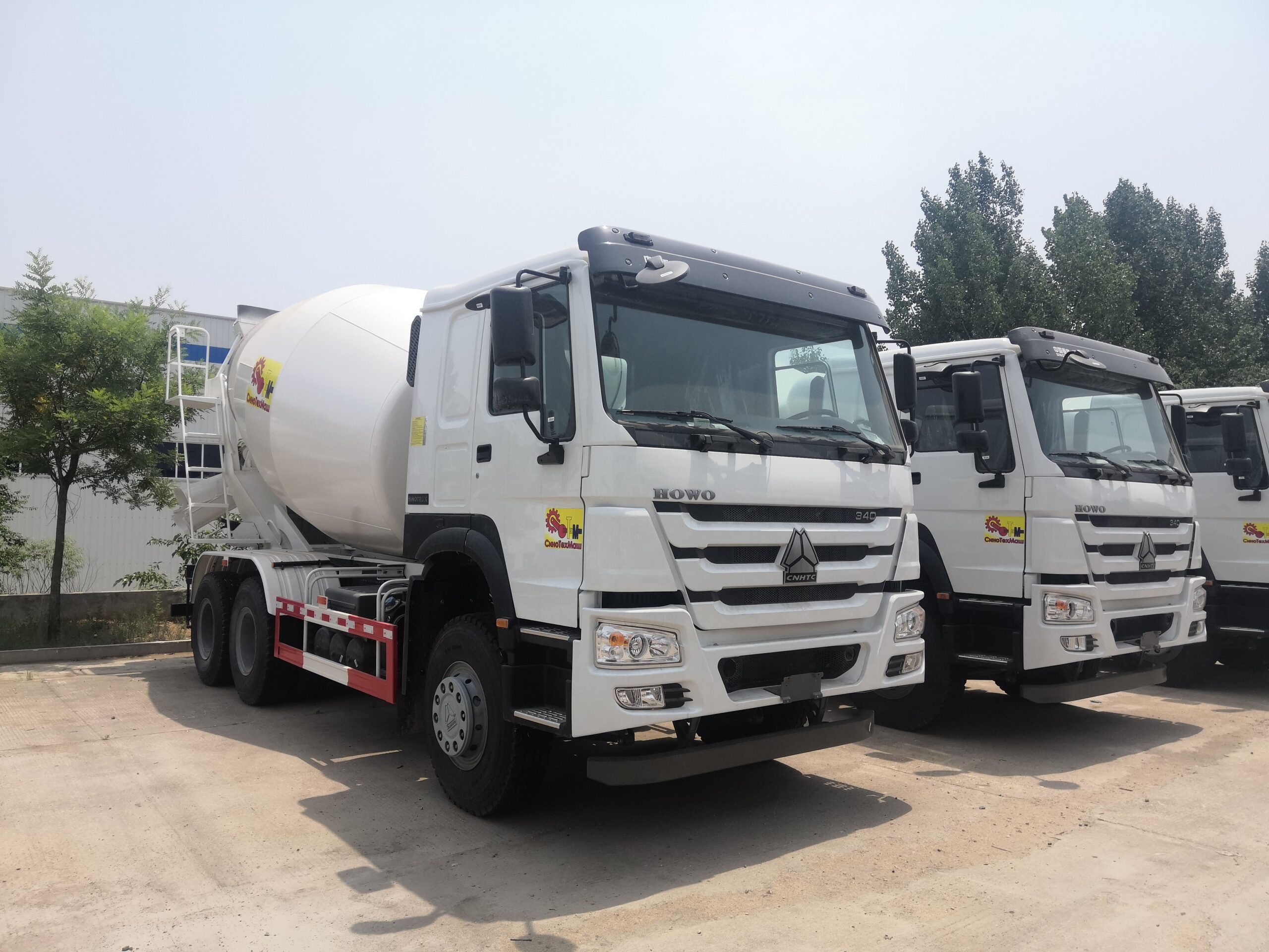
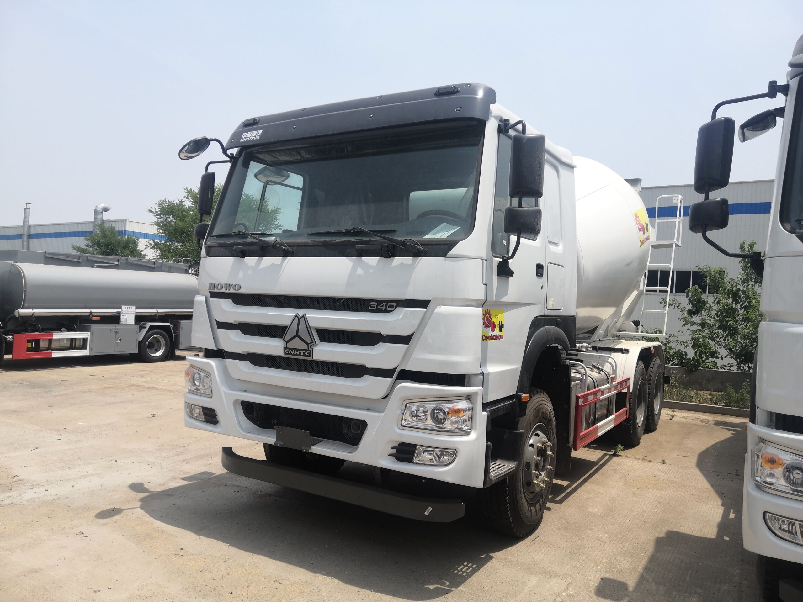
The mixer truck looks complex and essentially has only two cores: a sealed tank that can rotate forward and backward, and a hydraulic chain that turns engine power into low-speed, high torque rotation. The rest of the components are built around these two elements for support and assistance.
1、 Chassis – Load and Power Source
Adopting a second-class chassis modification, the frame needs to bear an additional load of nearly 20 tons of materials, so the strengthening of the chassis beam, the load-bearing capacity of the rear axle, and the size of the rear suspension are key. In addition to driving, the engine also extracts a second power from the gearbox or front end of the engine through a power take-off (PTO), which is supplied to the upper assembly for use. This route of power extraction is the starting point of energy for the entire vehicle’s installation work.
2、 Mixing drum – the most important component of the entire vehicle
The cylinder has a conical shape at the front and back, with a complete set of spiral blades welded to the inner wall, resembling a giant spiral from beginning to end. This set of blades is the entire mechanism for mixing and unloading: when rotating forward, it pushes the material deep into the cylinder, repeatedly lifting and dropping to complete the mixing; When reversing, the spiral material is sent out in reverse, which is also discharge. The axis of the cylinder is usually inclined at an angle of about 14 ° to the horizontal plane, and the discharge is completed by gravity combined with the blades. There is also a diversion structure inside the cylinder to prevent segregation.
3、 Transmission chain – from power take-off to gearbox
The power path is: power take-off → hydraulic pump → high-pressure oil pipe → hydraulic motor → reducer → cylinder. The hydraulic motor has high speed but low torque, and must be reduced in speed and increased in torque through a planetary gearbox to drive the fully loaded tank. Any mismatch in any link of this chain is manifested as’ inability to turn, unstable turning, and incomplete unloading ‘.
4、 Support and frame – three-point force
The cylinder is supported by three points: the front end is supported by the gearbox support, the middle and rear parts are supported by the supporting wheels or bearing seats on the subframe, and the subframe evenly transmits the load to the chassis beam. This structure determines the rigidity and smooth operation of the cylinder, and is also the most vulnerable area for cutting corners during modification.
5、 Incoming and outgoing equipment
The feeding hopper and feeding chute are located above the tail of the cylinder, responsible for receiving materials and guiding them into the tank; The discharge chute and the rotatable and adjustable chute are responsible for delivering concrete to the designated pouring point. The rotation angle, length, and hydraulic or manual adjustment method of the chute directly affect the convenience of on-site pouring.
6、 Water supply and cleaning system
Water tanks, water pumps, pipelines, and sprinkler systems are used to adjust slump as needed during transportation, as well as to flush the cylinder and inlet/outlet ports after operation. This part may seem inconspicuous, but it is the last line of defense to prevent canning.